Pages

Sunday, 26 January 2014

Client Server (TCP) programming

Before diving in the programming first we have to understand how TCP protocol works -

  1. It take your data, message, etc and break it in In segments and address them by adding destination address, source address etc in the header of the Message.
  2. Establish Connection between source and destination.
  3. Sends data over a Physical medium and wait for Acknowledgment from destination.
  4. If data packets lost (Acknowledgment not received in specified time) in between the data is resent.
  5. on receiving end data is arranged in sequence using header sequence of segment. 
  6. connection is closed.

Few key Terms of Network Programming:-

  • IP Address :- it is a unique number assigned to a node of a network e.g. 192.168.0.1 . It is composed of octets that range from 0 to 255. It is not your machine actual address (mac address) rather than it is the address your ISP provided to you. They maintain a table to work it out.
  • Port :- There are more than one application running on a machine.so It is a unique address which is used to identify the application which has to receive data, message, etc etc.

Programming Logic :-

  1. establish connection b/w Sender and receiver so they can talk to each other.
  2. send message .
  3. display message.
  4. Stop if connection is closed.

Prequest :-

  • Basic Understanding of programming logic and control structure (if,else,for etc).
  • Basics of java.

Programming :-


  • ServerSocket class is used to  acquire a port for application and getting the TCP connection.  ServerSocket  represents the Receiving end of communication.
  • Socket Represents the Connection and used to get data input output streams


  1. import java.io.*;  
  2. import java.net.*;  
  3.   
  4. public class MyServer {  
  5. public static void main(String[] args){  
  6. try{  
  7. ServerSocket ss=new ServerSocket(6666);  
  8. Socket s=ss.accept();//establishes connection   
  9.   
  10. DataInputStream dis=new DataInputStream(s.getInputStream());  
  11.   
  12. String  str=(String)dis.readUTF();  
  13. System.out.println("message= "+str);  
  14.   
  15. ss.close();  
  16.   
  17. }catch(Exception e){System.out.println(e);}  
  18. }  
  19. }  

Friday, 24 January 2014

Network Topology


What is Network Topology ?

Distributed computing systems have become the essential aspect of growing information technology. The performance of any distributed system is certainly influenced by the technology, which we adopt in making network interconnections. In mathematics topology is concerned with the connectedness of objects which is the most basic properties of space. In simple way network topology refers to the configuration of cables computers and other peripheral.

Each topology is suited to specific tasks and has its own advantages and disadvantages. A most simple and good example of network topology is LAN. Where it  has one or more physical links to other devices in the network. In recent days there are basically two basic categories of network topologies: Physical and Logical Topologies.

  1. Physical topologies 
Physical Network Topology emphasizes the hardware associated with the system including workstations, remote terminals, servers, and the associated wiring between assets. Physical topology defines how the systems are physically connected. It means the arrangement of devices on a computer network through the actual cables that transmit data. There are eight basic topologies.

Point To Point Topology

In a point-to-point link,  two devices monopolize a communication medium.  Because the medium is not shared,  a mechanism is not needed to identify the computers.  Therefore, a simple, two-device point-to-point network has no need for addressing.
Point-to-point links can be simplex, half-duplex, or full-duplex.  When devices must engage in bi-directional communication on a half-duplex link,  some turnaround mechanisms must be in place to switch the roles of the sending and receiving devices.

Bus Topology

In a bus topology, all devices attach to the same transmission medium. The medium has a physical beginning and end. All buses are implemented using electrical cable, usually coax, and the ends of the cable must be terminated with a terminating resistor that matches the impedance of the cable. The terminating resistor prevents data reflections from coming across as data corruption. The bus is considered a multipoint system because all devices tap into the same backbone cable.


An important characteristic to remember in bus topologies is that all data signals are broadcast throughout the bus structure.  In the following diagram, if first computer sends a signal to node last computer, the signal propagates for the length of the cable and is seen by all computers as well. It is necessary to have an addressing mechanism so that each node understands which messages it is to receive and which to ignore.

Benefits of Bus topology
Bus topology has the following advantage:
  • Cabling costs are minimized because of the common trunk.
Disadvantages of Bus topology
Disadvantages of bus topology are as follows:
  • Difficult to trouble shoot because no central distribution points exist.
  • Cable breaks can disable the entire segment because they remove the required termination from each of the two cable fragments.


Star Topology

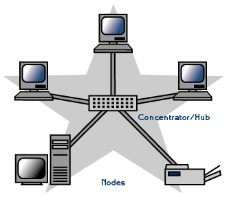
The star topology is a popular method of connecting the cabling in a computer network. In a star, each device connects to a central point via a point-to-point link. Depending on the logical architecture used, several names are used for the central point including the following:
  • Hub
  • Multipoint Repeater
  • Concentrator
  • Multi-Access Unit (MAU)

The central hubs also can be classified in the following manner:
  • Passive hub - A passive hub is a simple signal splitter. Its main function is to connect the arms of the star while maintaining the proper electrical characteristics.
    • A passive hub routes all traffic to all nodes. This means that a tremendous load can be created when much communication takes place between computers. Every computer has the additional burden of reading the address of each piece of information it receives to determine if the information is intended for that computer. Information containing other addresses are discarded.
  • Active hub - An active hub performs the same function as a passive hub, but contains electronic circuits that regenerate and retransmit the information. Thus, active hubs can be used to extend the size of a network.
  • Intelligent hub - Intelligent hubs perform the same functions as passive and active hubs; however, they can make informed path selections and perform some network management. Intelligent hubs route traffic only to the branch of the star on which the receiving node is located. If redundant paths exist, an intelligent hub can route information around normally used paths when cable problems occur.
    • Routersbridges, & switches  are examples of hub devices that can route transmissions intelligently. Intelligent hubs also can incorporate diagnostic features that make it easier to troubleshoot network problems.
Benefits of Stars
Most modern cabling systems are designed in a star physical topology. The benefits of the star topology are many, including the following:
  • Each device is isolated on its own cable. This makes it easy to isolate individual devices from the network by disconnecting them from the wiring hub.
  • All data goes through the central point, which can be equipped with diagnostic devices that make it easy to trouble shoot and manage the network.
  • Hierarchical organization allows isolation of traffic on the channel. This is beneficial when several, but not all, computers place a heavy load on the network. Traffic from those heavily used computers can be separated from the rest or dispersed throughout for a more even flow of traffic.
Disadvantages of Star topology
Star topology has the following disadvantages:


  • Because point-to-point wiring is utilized for each node, more cable is required.
  • Hub failures can disable large segments of the network.


Ring Topology


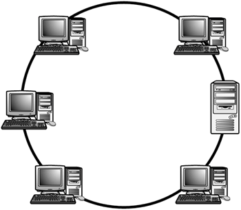
The ring topology is a physical, closed loop consisting of point-to-point links. In the diagram, you can see how each node on the ring acts as a repeater. It receives a transmission from the previous node and amplifies it before passing it on.

Benefits of Ring topology
Ring topology has the following advantage:
  • Each repeater duplicates the data signals so that very little signal degradation occurs.
Disadvantages of Ring topology
Ring topology has the following disadvantages:
  • A break in the ring can disable the entire network. Many ring designs incorporate extra cabling that can be switched in if a primary cable fails.
  • Because each node must have the capability of functioning as a repeater, the networking devices tend to be more expensive.

Mesh Topology

In this type of topology each device is interconnected with one another, allowing for most transmissions to be distributed even if one of the connections goes down. A major disadvantage is high chances of redundancy in many of the network connections and overall cost is too high compared to any other network topology. 

Benefits of Mesh topology

  •  Enhance for error tolerance provided by redundant links.
  •  Easy to troubleshoot.
Disadvantages of Mesh topology

  • Difficult to install and maintain.
  • Expensive.

Tree Topology


Tree Structure suits best when the network is widely spread and vastly divided into many branches. Tree topology is a combination of two or more bus and the Star Topology connected together. Each star network is a local area network (LAN) in which there is a central computer or server to which all the connected nodes directly linked. The central computers of the star networks are connected to a main cable called the bus. 

A major disadvantage is the length of the network depends on the type of cable that is being used and tree topology network is entirely dependent on the trunk which is the main backbone of the network. If that has to fail then the entire network would fail. 


Benefits of Tree topology
  • This topology is easy to control.
  • The root provides centralised management and monitoring.
Disadvantages of Tree topology
  • If the backbone cable breaks, the entire segment goes down.
  • The tree topology is difficult to configure, wire, and maintain, especially in extensive networks.

Hybrid Topology


Hybrid topology is a network topology that is composed of one or more interconnections of two or more networks that are based upon different physical topologies or a type of network topology that is composed of one or more interconnections of two or more networks that are based upon the same physical topology, but where the physical topology of the network resulting from such an interconnection does not meet the definition of the original physical topology of the interconnected networks. 

A major disadvantage is typically more expensive than other networks since it exploits the features of its component topologies. It requires more cabling between its hardware devices than other types of network topologies. Hybrid networks are difficult to set up and troubleshoot. 

Benefits of Hybrid topology
Hybrid topology has the following advantages:
  • One company can combine the benefits of several different types of topologies.
  • Workgroup efficiency and traffic can be customized.
Disadvantages of Hybrid topology
The disadvantages of hybrid topology include the following:
  • Devices on one topology cannot be placed into another topology without some hardware changes.

  1. Logical Topologies
Logical Network Topology emphasizes their presentation of data flow between nodes. It means logical topology is associated with the arrangement of devices on a computer network and how they communicate with one another. The main role of logical topology is to communicate across the physical topologies among different systems. There are two categories of logical topologies: Shared media topology and token-based topology.

Shared Media Topology

In shared media topology the systems have unrestricted access to the physical media that is all the systems in a network have the ability to access the physical layout whenever they need it. Collision is the main disadvantage of this topology as more than one system send information out on the wire at the same time, the packets collide and as a result this collision kills the packets. Ethernet is an example of a shared media topology. As a remedy some huge networks are broken down into smaller networks. Some ethernet uses Carrier Sense Multiple Access protocol to reduce the number of collisions. 


Token Based Topology

In token based topology a token is used which travels around the network to access the physical media. If any node wants to send a packet to another one it should wait for the token which is traverse within the network either clockwise or anti-clockwise direction. After getting the token a node can send the packet towards the network and all the nodes within the path from sender node to destination node, and all the intermediate nodes should check the destination address, if it matches to anyone it should accept the packet and generate an acknowledgement packet. Acknowledgement packet should follow the reverse path to acknowledge the sender node that the packet is received by the destination node. 


Wednesday, 22 January 2014

The OSI reference model

Open System Interconnect (OSI) Reference Model


Why Layer Model

  •  Reduces complexity
  •  Standardizes interfaces
  •  Facilitates modular engineering
  • Ensures interoperate technology Ensures interoperate technology
  •  Accelerates the evolution of network technology.
  • Simplifies teaching and learning

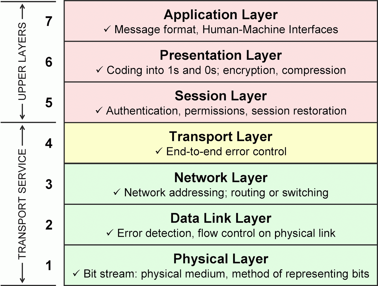
OSI Model – Physical Layer

  • deals with mechanical, electrical and procedural interfacing.
  • specifies cables, connectors, and other components.
  • transmits raw information over communication channel communication channel.
  • establishes, maintains, and disconnects physical links physical links.

OSI Model – Data Link Layer

  •  provides reliable transfer of data  
  • breaks data (packets) into frames
  • adds bits for error detection/correction
  • manages access to and use of the manages access to and use of the channel
  • solve problems caused by lost, damaged, and duplicate frames
  • sends acknowledgments
  • adds flags to indicate beginninand end of message
  • connectionless or connection oriented connectionless or connection oriented services
  • IEEE MAC and LLC support

      OSI Model – Network Layer

      • establishes, maintains and terminates connections
      • determines how packets are routed
      • divides transport messages into packets divides transport messages into packets and reassembles them 
      • performs congestion control flow control performs congestion controlflow control.
      • provides virtual circuit or datagram services 
      • recognizes message priorities
      • sends messages in proper order
      • handles internetworking
                  OSI Model – Transport layer


                    • establishes reliable end-to-end transport session (error detection and recovery), once path has been established
                    • fragmentation of message into packets (if not handled by layer 3)
                    • multiplexing of several sessions from multiplexing of several sessions from same source and all going to same destination

                        OSI Model – Session layer

                        • establishes and terminates connections
                        • accounting service
                        • authentication of users 
                        • controls dialogue, organizes and synchronizes

                          OSI Model – Presentation layer


                            • data encryption, security, compression and code conversion
                            • make sure data is encoded in standard form ( ASCII) 
                            • handles pass-through of services from session to application layer session to application layer

                                OSI Model – Application layer

                                •  login, password check
                                • agreement on semantics for information exchange
                                • file transfer access and management file transfer, access and management
                                • message handling, email 
                                • job transfer and manipulation
                                • directory service 


                                Tuesday, 12 March 2013

                                Communication

                                History of Computer Network

                                Today's computer network is the Internet communication network 60 in this field in the early telephone network was a trace at the beginning of World authority. Internet World is the source of the advanced research network (ARPANET) of the U.S. Defense Department was in 1969. Things to see of growth in the last 35 year of the computer network. 
                                In 1974 Ethernet was to be verified at the Xerox PARC Alto computer network. And after in 1978 the modem dial up connection was being introduced 
                                after 1978 in 1981 – the new TCP /, UNIX operating system was being released of the IP suite. The first portable computer and it was promoted in size of almost a pound suitcase 
                                In 1981, PC are being promoted from IBM and after that in 1982 TCP / IP (Transmission Control Protocol and Internet Protocol) were created for normal ARPANET And in the TCP was used to regulate the ARPANET / IP protocol which was taken up by Pentagon. 
                                In 1986 the protocol TCP / IP were to be introduced with the new Compaq workstation PC and in 1987 the network host break had crossed almost 100000 and in 1989 it crossed the host almost 1000000 and in 1990 the ARPANET was being stopped and many other tools like Gopher were being introduced in 1991 the ARPANET was being changed to NFSnet as the major government network linking research institution and NFSnet was being advance to T3 and even the world wide web was being developed and directed by lee and the CERN acted as the first main web server in 1991.
                                By 1992 the internet was very familiar worldwide to everyone in the form of www.

                                Component of Computer Network

                                There are five component in a computer network.


                                • Message:- Message is consist of information that a user of computer network wants to transmit it to the other computer in the network.it may be Text, Image, Video or Audio.

                                • Sender:- Sender is the device which send the message . It may be a computer, smartphone, workstation or video camera.

                                • Receiver:- Receiver is the device that receive the massage. It may be a Radio, T.v, Computer, smartphone or printer.

                                • Transmission medium:- Transmission medium is a physical by which a message flow from sender to receiver. It may be wired or wireless eg. radio wave, micro wave, twisted pair wire co axial cable or fiber optics.

                                • Protocol:- A Protocol is set of rule that governs the data communication. Protocol is the most essential part of computer network. Without protocol two computer can be connected but they can not communicate to each other.

                                Data Flow

                                There are three types of Data flow in a computer network.

                                1. Simplex mode:- In this mode the data can flow in only one direction. The sender never play the role of receiver and receiver never play the role of sender. eg. Keyboard, Mouse, radio , television are the examples of the simplex data flow.
                                2. Half Duplex:- Data can flow in either direction --from sender to receiver or receiver to sender but only in one direction at a time. eg. Walky-talky, Fax machine, ATM.
                                3. Full Duplex:- Data can Flow either direction --from sender to receiver and receiver to sender simultaneously. 

                                Types of Connection

                                In a network two or more devices are connected through links.There are two possible way to connect the devices they are follow:-

                                1. Point-to-Point connection:- A point to point connection provide a dedicated link between two devices as shown in figure

                                1. Multipoint connection:- A multipoint connection also called multidrop connection. In such a communication more than two devices share a single link as shown in figure. In the multipoint connection the channel capacity is sheared. If many devices share the link simultaneously, it is called spatically shared connection but if user share the link turn  by turn than it is time sharing connection.